FSAE
The Team
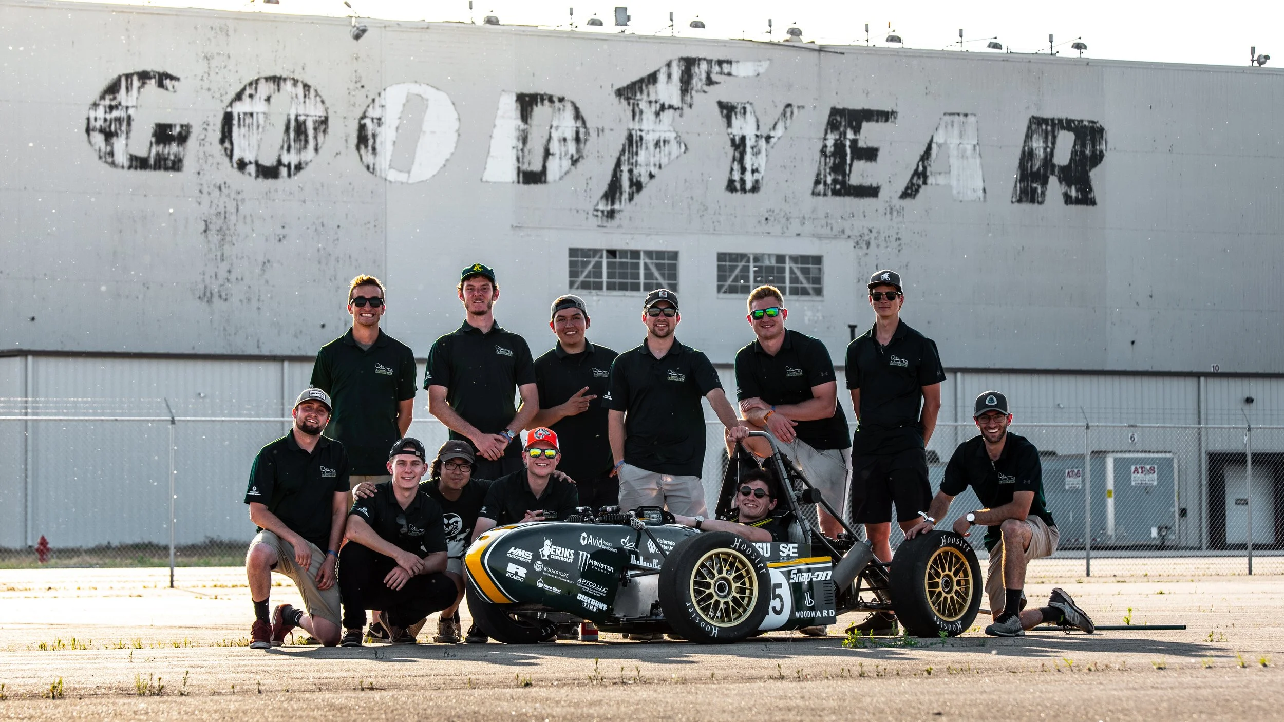
The 2018-2019 Ram Racing Team. A mashup of passionate engineers, good dudes, and the hardest working guys I’ve ever known. An absolute pleasure to work with.
The RR19
Ram Racing’s (Colorado State University’s FSAE team) car built by our small team for the 2019 season.
In just 12 months, we were challenged to design, build, and test an open wheeled single-seater race car to then compete with other teams at a national competition.
This is the first successful Ram Racing car after a 3-year team hiatus. From 2016 - 2018, electric cars were attempted, but none completed in time for competition. For the 2019 season, us seniors had our hands full: we had to revive the team, recruit members, gain sponsors, as well as build the car.
RR19 at testing facility, aero removed.
My Area of Focus: Drivetrain
Rear part of the car housing my pride and joy: the drivetrain package. As Drivetrain Lead, I was tasked with project management duties for our team of 3 people, as well as design and build the intake + exhaust systems, cooling system, fuel system, component packaging, and mounting systems.
Notice the longitudinal engine layout and shaft drive (no chain). We were the only team to run this configuration at competition in Lincoln, NE.
Solidworks 3D CAD of entire engine package.
This is the representation of the Yamaha R6 engine in the 1-D engine simulation software Ricardo WAVE (an industry-grade engine sim platform). This software allows the user to change parameters of the engine virtually. It will then spit out info on the resulting effects to the engine, such as horsepower and torque curves.
With this software, I was able to virtually change the lengths of the intake and exhaust runners and see the effects of these changes on the torque curve. This is called intake and exhaust tuning and takes advantage of the fascinating and complex phenomenon of pressure waves traveling up and down the runners as the engine runs. The runners will resonate at certain rpm’s - similar to a musical instrument creating sound.
The ultimate goal for this design was to create an engine that performs with a flat torque curve over a large range of engine speeds, while not compromising too much on peak torque. This leads to a linear relationship between the travel of the gas pedal and the power output of the engine, and results in a car that is easier to drive fast.
This is the resulting torque versus engine speed plot that Ricardo WAVE outputted for my final intake and exhaust designs.
For verification of this design, a real-word dynamometer test was done. However, problems with the dyno led to testing only able to be done to about 8,000rpm (redline is at 13,500rpm). For this reason, I added the black line which shows my predicted real-world torque curve.
This graph shows 30 different simulations in the Ricardo WAVE software, and the resulting characteristics. This is the Design of Experiments (DOE) method which made it very easy to find the optimal lengths of intake and exhaust runners.
From runs 1 to 30, I increased the length of the intake and exhaust runners by 50mm. The yellow-highlighted area shows the run number (which corresponds to an intake and exhaust length) that gives me both the highest peak torque and the widest range of engine speeds in which the flat torque curve is present. With the help of this plot, I was able to easily choose the optimal intake and exhaust runner length for our goals: a wide torque band that does not sacrifice too much on peak torque.Intake Manifold
CAD of final intake manifold design. From the above tests, the final optimal intake runner length was found to be 250mm.
Cut-away of intake manifold showing interior features.
Intake manifold fresh from the 3D printing shop who partnered with us. Printer: HP MJF. Material: Nylon PA-12.
Exhaust Manifold
Solidworks CAD of equal-length tubular exhaust manifold. Ideal runner length chosen from previously-discussed Ricardo WAVE experiments.
This is the CAD-modeled exhaust jig and the real life version created with 8020 extruded aluminum. The jig features a 3D printed part to mimic the exact location of the engine's exhaust ports, and 2 accurately located chassis tubes that the exhaust runners needed to avoid.
Here is the manifold with all pieces cut and tacked together by me. Later, a teammate who is more skilled at welding, completed the welds around the joints.
Final product installed onto engine. This exhaust manifold is easily the most challenging and rewarding fabrication project I’ve ever completed.
Engine Tuning
Myself and two other teammates collaborated to tune the engine's parameters via TunerStudio_MS. Ignition was tuned for reliability - conservatively away from knocking conditions. Fuel maps were tuned for slightly richer air/fuel ratios than stoichiometric, over all engine speeds and loads.
Other Drivetrain Components
Aluminum fuel tank. Designed by me: includes heavily baffled interior and uses the stock Yamaha fuel pump assembly installed from bottom. Pieces were cut at a local waterjet company, and later bent and welded together.
Custom baffled oil pan which I helped design.
Custom baffled, low profile oil pan which I helped design.
Junior-year FSAE Projects
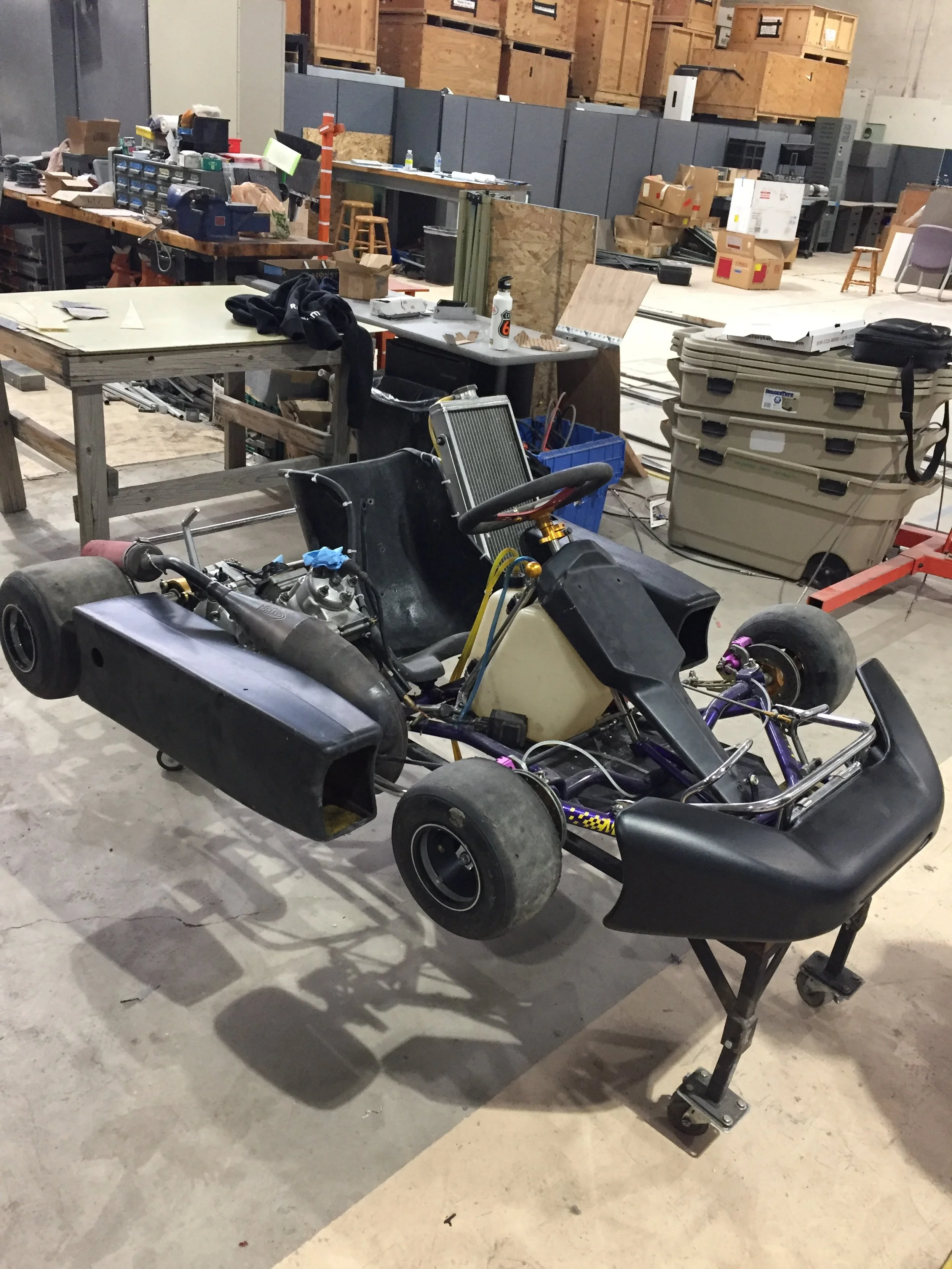
In the 2017/2018 school year, I was a junior on the Ram Racing FSAE team. Here I was tasked with reviving the 2-stroke yz125 Yamaha engine on the team's old shifter kart. I repaired the cylinder, installed a diaphragm powered fuel system, sourced and tuned a new carburetor, and fixed the wiring harness. The kart was running within a couple months.


